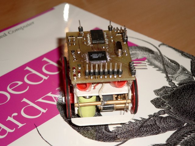
To date, this is my most successful design. It is powered by an Atmel 8535, which means you can write fairly complex applications (8Kb flash). It has 4 tactical sensors, two eyes based on LDR resistors placed in a tube to have directional sensory, one RC5 Ir diode to be able to command the robot using a standard remote control unit and expansion bus on the top of the vehicle (Wireless module has been build).

Introduction
This small robot measures 75x38x50 mm, and is powered by two geared DC motors. Four NiMH cells, delivering 120mAh at 1.2 V each provide enough power for approximately 1 hour autonomy. The brains of the robot are made up of a AT90LS8535 running at 4MHz in a TQFP package. The motors are driven by a 74AC244, an octal buffer/line driver which I used to make 2 H-bridges.
The robot has 8 sensors; 4 touch sensors on each corner, two directional LDR light sensors, one IR sensor (TSOP1736, RC5 type) and one proprioceptive sensor indicating battery status. This sensor package seems to be enough to provide for rather intelligent behavior.
The robot has a tank like locomotion. I’ve grown fond of this type of locomotion as it provides traction on all wheels. Also, I really enjoy the skid steering.
The robot has 4 connectors; one to charge the batteries, another one to program the robot, a serial connector and one expansion bus, exposing 8 data lines, from which 4 our ADC capable. I’ve build a wireless module to put on top of the robot. More on that will follow, sufficient to say now that it uses a BIM2 transceiver from radiometrix. I’ve experienced some troubles getting the PCB ready for the PC host adapter, as I had to redo the PCB for a few times to get it right. Hence, I put the wireless module on a lower priority.

Schematic
 {: dither=“no” }
Sample code
The next code is a small BASCOM program that can drive the MicroRover. It is a simple subsumption architecture, using 3 behaviors; photofobic, wandering and react to touch.
Subsumption
 {: dither=“no” }
You can read more about the subsumption architecture in the following wikipedia article about subsumption architecture.
Code
:::basic
'(
r o v e r
---------
test code for rover based on 8535
')

M1A alias portd.7
M1B alias portd.6

M2A alias portc.1
M2B alias portc.0

BAT_CONTROL alias portc.4
const BAT_LEVEL = 5

TOUCH_BACK_LEFT alias pinc.5
TOUCH_BACK_RIGHT alias pinc.6
TOUCH_FRONT_LEFT alias pind.4
TOUCH_FRONT_RIGHT alias pind.5

EYE_CONTROL alias portc.7
const EYE_LEFT = 7
const EYE_RIGHT = 6

config Adc = Single , Prescaler = Auto
config debounce = 10
config Rc5 = pind.2
enable interrupts

' -- subroutine declarations
declare sub forward
declare sub backward
declare sub turn_left
declare sub turn_right
declare sub halt
declare sub diagnostics

declare sub motor

declare sub touch
declare sub photofoob
declare sub wander

' -- variable declarations
dim eye_l as  Word
dim eye_r as  Word
dim bat as Word
dim tch_bl as bit
dim tch_br as bit
dim tch_fl as bit
dim tch_fr as bit

dim c as byte
dim rc5_address as byte, rc5_command as byte
dim temp as byte
dim i as integer

' -- define behaviours

'  . global settings
const BEAT  = 50           ' -- unit of execution time
                         '  a behaviour will use this as a standard
                         '  time tick for action
const BEAT2 = 100

'  . touch
dim touch_state as byte    ' - state of the 'touch' behaviour
dim touch_dur as word      ' - duration
dim touch_turn as byte
dim touch_direction as byte

'  . motor
dim motor_vector as byte   ' - drive vector for motors
const M_STOP = 0
const M_FORWARD = 1
const M_RIGHT = 2
const M_BACK = 3
const M_LEFT = 4

' . photofoob
dim photofoob_state as byte
dim photofoob_turn as byte
dim photofoob_dur as word
dim photofoob_offset as word

'  . wander
dim wander_state as byte
dim wander_turnorgo as bit
dim wander_dur as long
const WANDER_RUN = 200*BEAT

' -- main
DDRD = &B11001011
DDRC = &B10011111

start Adc

set PORTC.6
set PORTC.5
set PORTD.5
set PORTD.4

wander_state = 0
photofoob_state = 0
photofoob_offset = 50
touch_state = 0
motor_vector = 0

do
 ' pull in data from the sensors
 gosub latch_sensors

 ' behaviours
 photofoob
 wander
 touch

 ' override controls now with RC5 commands
 ' gosub remote

 ' motor control
 motor

 temp = inkey()
 if temp > 0 then
    call diagnostics
 end if

loop

' -- control the engine
sub motor
 select case motor_vector
    case M_STOP:
       call halt
    case M_FORWARD:
       call forward
    case M_BACK:
       call backward
    case M_LEFT:
       call turn_left
    case M_RIGHT:
       call turn_right
 end select
end sub

' -- Pull the sensory data into globals
latch_sensors:
 set EYE_CONTROL
 waitus 250
 c = EYE_LEFT
 eye_l = getadc(c)
 c = EYE_RIGHT
 eye_r = getadc(c)
 reset EYE_CONTROL

 set BAT_CONTROL
 waitus 250
 c = BAT_LEVEL
 bat = getadc(c)
 reset BAT_CONTROL

 tch_bl = TOUCH_BACK_LEFT
 tch_br = TOUCH_BACK_RIGHT
 tch_fl = TOUCH_FRONT_LEFT
 tch_fr = TOUCH_FRONT_RIGHT

 return

' --
remote:
 getrc5( rc5_address, rc5_command)
 if rc5_address <> 255 then
    rc5_command = rc5_command and &B10111111
    select case rc5_command
       case 32:
          motor_vector = M_FORWARD
       case 33:
          motor_vector = M_BACK
       case 16:
          motor_vector = M_RIGHT
       case 17:
          motor_vector = M_LEFT
       case 12:
          motor_vector = M_STOP
       case 14:
          call diagnostics
    end select
 end if
 return

' -- print out some diagnostics
sub diagnostics
print "el  "; eye_l
print "er  "; eye_r
print "ba  "; bat
print "wd  "; wander_dur
print "bl "; tch_bl
print "br "; tch_br
print "fl "; tch_fl
print "fr "; tch_fr
print "vc "; motor_vector
end sub

' -- move forward
sub forward
 set M1A
 reset M1B
 set M2A
 reset M2B
end sub

' -- move backward
sub backward
 reset M1A
 set M1B
 reset M2A
 set M2B
end sub

' -- turn right
sub turn_right
 set M1A
 reset M1B
 reset M2A
 set M2B
end sub

' -- turn left
sub turn_left
 reset M1A
 set M1B
 set M2A
 reset M2B
end sub

' -- stop rover
sub halt
 reset M1A
 reset M1B
 reset M2A
 reset M2B
end sub


' ------------------------------------------------------------------------
' --    B E H A V I O U R S
' ------------------------------------------------------------------------

sub touch
 ' we always react to touch, even when processing a touch
 if tch_bl = 0 then
    touch_turn = M_RIGHT
    touch_direction = M_FORWARD
    touch_state = 1
    touch_dur = BEAT2
 end if

 if tch_br = 0 then
    touch_turn = M_LEFT
    touch_direction = M_FORWARD
    touch_state = 1
    touch_dur = BEAT2
 end if

 if tch_fl = 0 then
    touch_turn = M_RIGHT
    touch_direction = M_BACK
    touch_state = 1
    touch_dur = BEAT2
 end if

 if tch_fr = 0 then
    touch_turn = M_LEFT
    touch_direction = M_BACK
    touch_state = 1
    touch_dur = BEAT2
 end if

 select case touch_state

 case 0:

 case 1:
    motor_vector = touch_direction
    if touch_dur = 0 then
       touch_state = 2
       touch_dur = BEAT2
    end if
    decr touch_dur

 case 2:
    motor_vector = touch_turn
    if touch_dur = 0 then
       touch_state = 0
       touch_dur = 0
       motor_vector = M_STOP
    end if
    decr touch_dur

 end select
end sub

sub photofoob
 select case photofoob_state

 case 0:
    ' we kick into action when it is too light
    if eye_l > photofoob_offset or  eye_r > photofoob_offset then
       photofoob_turn = M_LEFT
       if eye_l > eye_r then
          photofoob_turn = M_RIGHT
       end if
       photofoob_dur = BEAT
       photofoob_state = 1
    end if

 case 1:
    motor_vector = photofoob_turn
    if photofoob_dur = 0 then
       photofoob_state = 2
       photofoob_dur = BEAT
    end if
    decr photofoob_dur

 case 2:
    motor_vector = M_FORWARD
    if photofoob_dur = 0 then
       photofoob_state = 0
       motor_vector = M_STOP
    end if
    decr photofoob_dur

 end select
end sub

sub wander
 select case wander_state

 case 0:
    i = rnd(100)
    i = i * 10
    wander_dur = i * BEAT
    wander_state = 1

 case 1:
    if wander_dur = 0 then
       wander_state = 2
       wander_turnorgo = 0
       wander_dur = WANDER_RUN
    end if
    decr wander_dur

 case 2:
    if wander_turnorgo = 0 then
       motor_vector = M_LEFT
       if eye_l < eye_r then
          motor_vector = M_RIGHT
       end if
    else
       motor_vector = M_FORWARD
    end if
    if wander_dur = 0 then
       wander_state = 0
       motor_vector = M_STOP
    end if
    decr wander_dur
    i = wander_dur mod BEAT2
    if i = 0 then
       toggle wander_turnorgo
    end if

 end select
end sub
The most primitive behavior is reaction to touch, this behavior can subsume over all other tasks. Most of the time, the robot is in a photofobic state, it will wander of to a dark place by constantly steering in the most dark direction. Light values are measured by an ADC channel on the AVR MPU. Whenever the robot reads the light intensity on its two eyes, it’ll power the LDRs for a short time and - enough time for the ADC to setlle - and then read out the intensities (lines 149-155). This intermittent powering of the LDRs prevent battery drain. When the light intensities falls below a certain threshold, the robot will sit happy until light levels are up again.
Whenever an object hits one of the touch sensors, the robot will try to turn away from the obstacle by reversing its direction and turning towards the opposite site of the touched sensor. If both front or aft sensors are touched, the robot just reverses direction, no turn takes place (lines 250-302).
After a random time, the rover wants to wander around. This wandering behavior has priority over its photofobic state, but lower priority than the touch behavior. When in wandering state, the robot is attracted to light. It will run of as fast as it can to brightest spot it can detect. The time that the robot wanders around is determined by another random number. I’ve found that this wandering state is very usefull for the robot to roam the complete room. If the wandering behavior would not be included, the robot would simply drive to a dark spot and sit there until light intensities are high enough to get it moving again. With the wandering behavior, though, the robot can sit idle on a dark spot, come to life again and run straight into the light. When the wandering behavior shuts down, the robot gets a panic attack and hurries to the nearest dark spot it can find (lines 337-374).
Lines 171 to 190 implement code to steer the robot via a TV remote control. The remote control can steer the robot in all 4 directions. Moreover, it can let the robot dump its internal state to its serial port. This can come in handy when debugging.
Although the battery level is already measured (lines 157-161) , by comparing a constant voltage drop over 3 diodes against the battery voltage, nothing is done with it. The idea is to have a small hardware extension on the robot that allows it to charge automatically. This extension can be made of just two wires that can connect to a docking station, composed of two metal plates. The idea is to let the robot navigate to a charging station as soon as battery levels drop below a certain treshhold. Moreover, the idea is to use the LDRs to navigate to the charging station. A LED, pulsating at a low enough frequency can be easily detected by the LDRs. The LED would indicate the position of the charging station.
Some images


[